The picture scripts represent a separate external module of Ingenious.V12 that you can buy at the Ingenious GmbH. To install the module just copy the plugin into your Ingenious.V12 directory.
With the help of the picture scripts you can create scaled and flexible sketches for your items.
To open the module click in the window “Service items / measurement sheets” on the button “Switch to measurement pictures” ![]() . A new window will open up where you have the opportunity to create several picture scripts and add pictures.
. A new window will open up where you have the opportunity to create several picture scripts and add pictures.
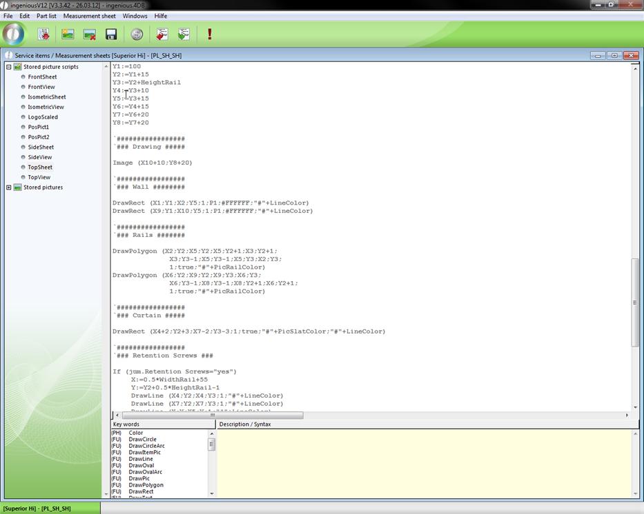
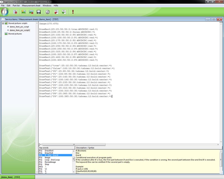
Example of a picture script
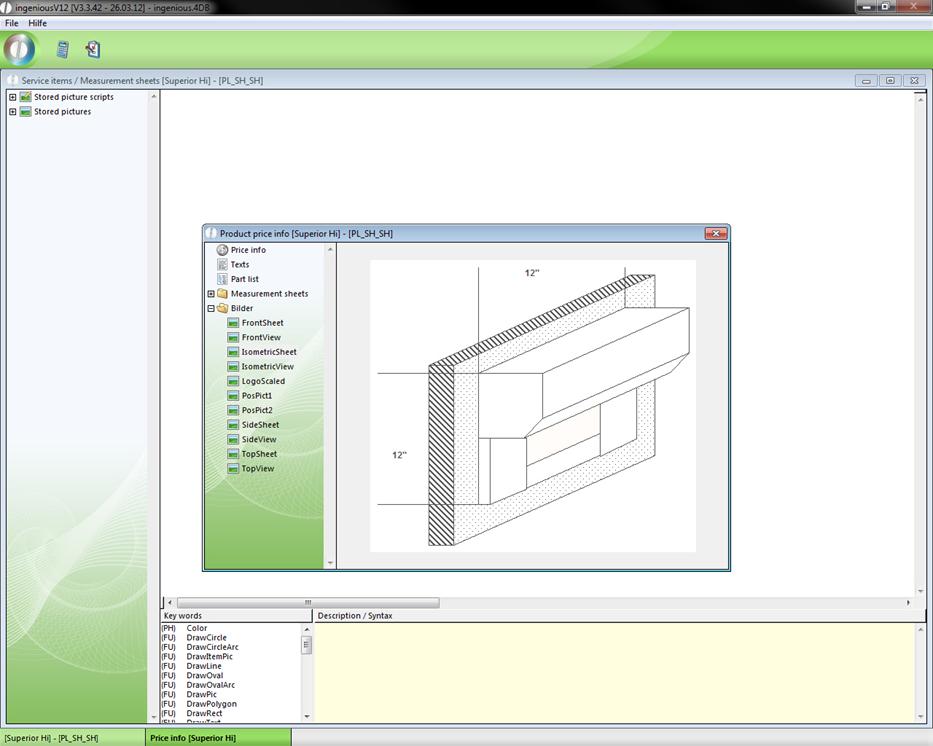
To access the current picture script you have to click the button ![]() .
.
Then click on ![]() and create a valid configuration.
and create a valid configuration.
Now you can go to the directory “Pictures” and find the measurement picture created to the picture script.
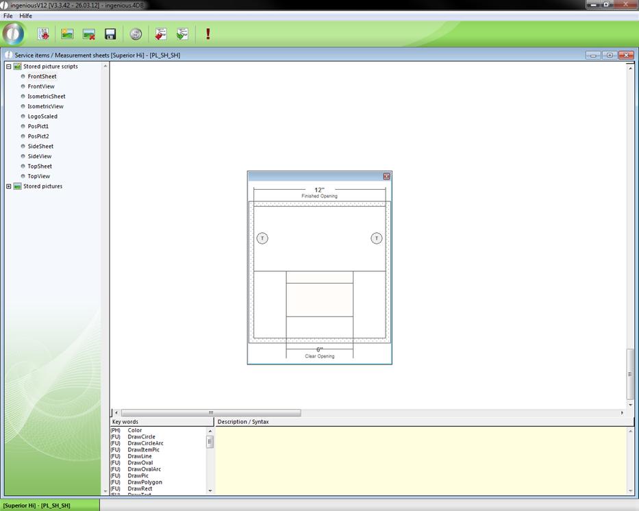
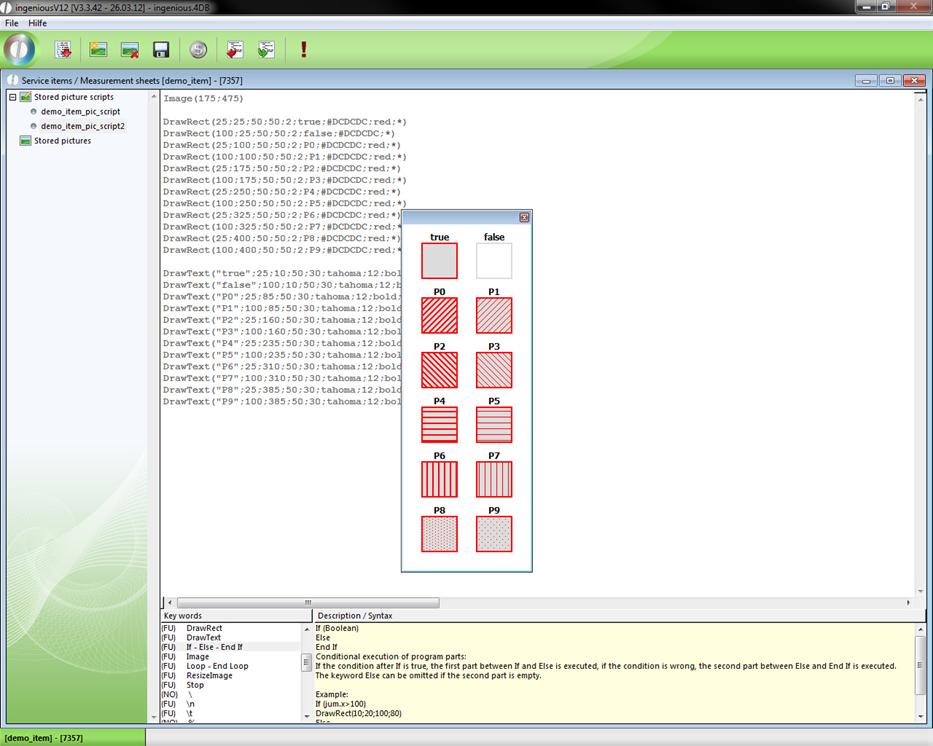
The current measurement picture can also be displayed in the “measurement pictures” window with the button ![]() “Run script!”.
“Run script!”.
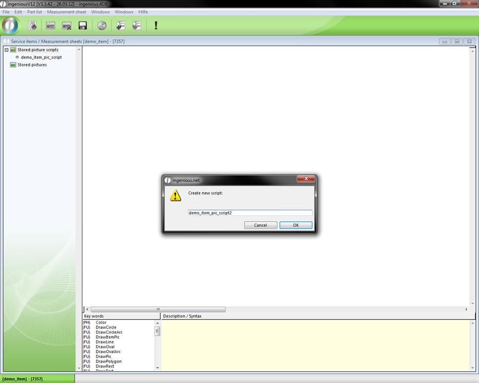
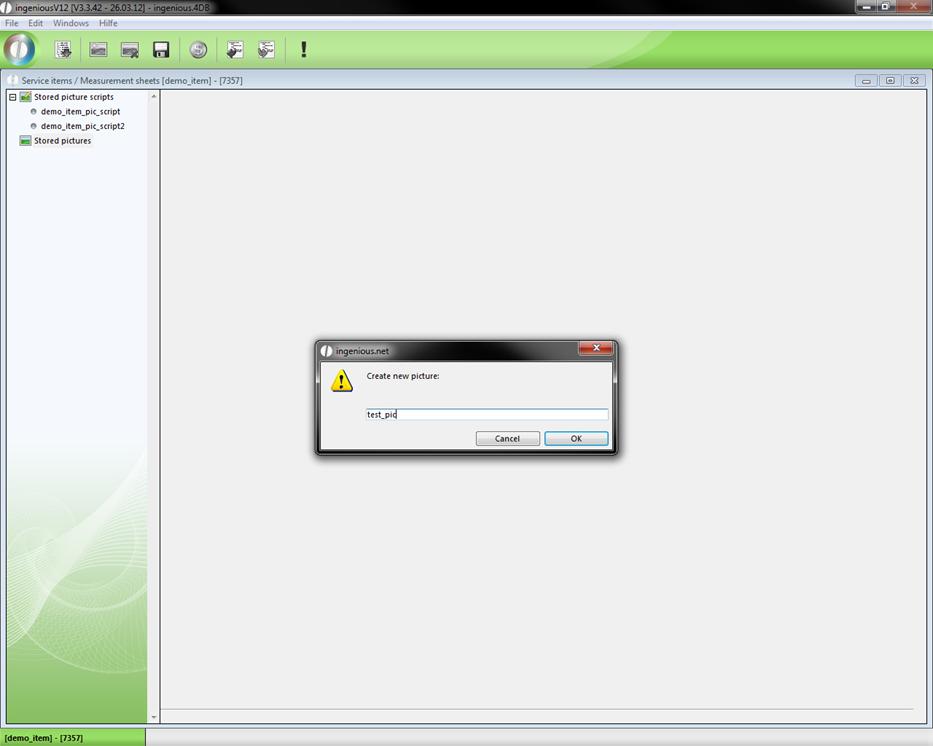
To create a new picture script click on the button ![]() . In the appearing window you can enter a script name.
. In the appearing window you can enter a script name.
The script creation happens in the script area. With a double click you can add the desired key word and alter it. Every key word is described in the right window area. On this way you can create you individual picture scripts quick and easy.
It’s also possible to fill areas with a pattern and to set the background and line color. There are 10 different patterns with fixed parameter names (P0 – P9). In the following representations a few script command variations for the different patterns and the visual output is displayed.
A few important key words to create picture scripts:
Color
Syntax: #FFFFFF
The following colors can be used to colorize objects: black; darkgrey; grey; lightgrey; white; red; green; blue; yellow; cyan; magenta; orange; purple; brown.
Other colors can be insert by RGB-values in hexadecimal form: #RRGGBB.
Example: very light grey: #e0e0e0
DrawCircle
Syntax: DrawCircle (X1;Y1;Radius{;Width{;Filled{;Color1{;Color2}}}})
Create a circle:
The center of the circle is at X1 / Y1, the distance between circle and center is specified by Radius.
The parameter "Width" specifies the width of circle line (optional, default: 1).
The parameter "Filled" specifies whether the interior of the circle is transparent or filled with a pattern (optional, default: False).
The parameter "Color1" specifies the color of the circle (optional, default: black).
The parameter "Color2" specifies the line color of a filled circle (optional, default: black).
Example: DrawCircle (100;100;75;1;False;blue)
DrawCircleArc
Syntax: DrawCircleArc (X1;Y1;Radius;StartAngle;ArcAngle{;Width{;Filled{;Color1{;Color2}}}})
Create a segment of a circle:
The center of the circle is at X1 / Y1, the distance between segment and center is specified by Radius.
The parameter "StartAngle" specifies where the starting point of the segment is, 0° is vertical over the center, 90° is right of the center, etc..
The parameter "ArcAngle" specifies the size of the segment.
The parameter "Width" specifies the width of circle line (optional, default: 1).
The parameter "Filled" specifies whether the interior of the segment is transparent or filled with a pattern (optional, default: False).
The parameter "Color1" specifies the color of the segment (optional, default: black).
The parameter "Color2" specifies the line color of a filled segment (optional, default: black).
Example: DrawCircleArc (100;100;75;-45;90;1;False;blue)
DrawItemPic
Syntax: DrawItemPic (Matchcode;X1;Y1{;X2;Y2{;*}})
Create a item picture:
The upper left corner of the picture is at X1 / Y1.
The picture can be scaled with the parameters X2 / Y2. If these parameters are omitted the picture is printed in orginal size.
If the * is omitted, the lower right corner of the picture is at X2 / Y2, otherwise it's at X1+X2 / Y1+Y2 (optional).
Example: DrawItemPic (Item X;10;60;100;100;*)
DrawLine
Syntax: DrawLine (X1;Y1;X2;Y2{;Width{;Color}}{;*})
Create a line:
The starting point of the line is at X1 / Y1.
The end point of the line is at X2 / Y2 if * is omitted, otherwise it's at X1+X2 / Y1+Y2.
The parameter "Width" specifies the width of the line (optional, default: 1).
The parameter "Color" specifies the color of the line (optional, default: black).
Example: DrawLine (10;10;50;50;1;red;*)
DrawOval
Syntax: DrawOval (X1;Y1;X2;Y2{;Width{;Filled{;Color1{;Color2}}}}{;*})
Create a ellipse:
One corner point of the ellipse is at X1 / Y1.
If the * is omitted, the second corner point of the ellipse is at X2 / Y2, otherwise it's at X1+X2 / Y1+Y2.
The parameter "Width" specifies the width of line (optional, default: 1).
The parameter "Filled" specifies whether the interior of the ellipse is transparent or filled with a pattern (optional, default: False).
The parameter "Color1" specifies the color of the ellipse (optional, default: black).
The parameter "Color2" specifies the line color of a filled ellipse (optional, default: black).
Example: DrawOval (100;100;175;130;1;False;blue)
DrawOvalArc
Syntax: DrawOvalArc (X1;Y1;X2;Y2;StartAngle;ArcAngle{;Width{;Filled{;Color1{;Color2}}}}{;*})
Create a ellipse segment:
One corner point of the ellipse is at X1 / Y1.
If the * is omitted, the second corner point of the ellipse is at X2 / Y2, otherwise it's at X1+X2 / Y1+Y2.
The parameter "StartAngle" specifies where the starting point of the segment is, 0° is vertical over the center, 90° is right of the center, etc..
The parameter "ArcAngle" specifies the size of the segment.
The parameter "Width" specifies the width of line (optional, default: 1).
The parameter "Filled" specifies whether the interior of the ellipse segment is transparent or filled with a pattern (optional, default: False).
The parameter "Color1" specifies the color of the ellipse segment (optional, default: black).
The parameter "Color2" specifies the line color of a filled ellipse segment (optional, default: black).
Example: DrawOvalArc (100;100;175;130;-45;90;1;False;blue)
DrawPic
Syntax: DrawPic (Name;X1;Y1{;X2;Y2{;*}})
Create a picture:
The upper left corner of the picture is at X1 / Y1.
The picture can be scaled with the parameters X2 / Y2. If these parameters are omitted the picture is printed in orginal size.
If the * is omitted, the lower right corner of the picture is at X2 / Y2, otherwise it's at X1+X2 / Y1+Y2 (optional).
Example: DrawPic (Pic1;10;60)
DrawPolygon
Syntax: DrawPolygon (X1;Y1;X2;Y2{;X3;Y3;...}{;Width{;Filled{;Color1{;Color2}}}})
Create a polygon:
The start point of the polygon is at X1 / Y1.
The parameter "X2; Y2; X3; Y3; ..." specifie the corner points of the polygon.
The parameter "Width" specifies the width of the border lines (optional, default: 1).
The parameter "Filled" specifies whether the interior of the polygon is transparent or filled with a pattern (optional, default: False).
The parameter "Color1" specifies the color of the polygon (optional, default: black).
The parameter "Color2" specifies the line color of a filled polygon (optional, default: black).
Example: DrawPolygon(80;140;120;140;160;170;1;True;green;gray)
DrawRect
Syntax: DrawRect (X1;Y1;X2;Y2{;Width{;Filled|Pattern{;Color1{;Color2}}}}{;*})
Create a rectangle:
One corner point of the rectangle is at X1 / Y1.
If the * is omitted, the second corner point of the rectangle is at X2 / Y2, otherwise it's at X1+X2 / Y1+Y2.
The parameter "Width" specifies the width of the border lines (optional, default: 1).
The parameter "Filled" specifies whether the interior of the rectangle is transparent or filled with a pattern (optional, default: False).
The parameter "Color1" specifies the color of the rectangle (optional, default: black).
The parameter "Color2" specifies the line color of a filled rectangle (optional, default: black).
Example: DrawRect (10;10;50;50;1;P3;red;blue;*)
DrawText
Syntax: DrawText (Text;X1;Y1{;X2;Y2}{;Font{;Size{;Style{;Alignment{;Color}}}}}{;*})
Create a text:
The upper left corner of the picture is at X1 / Y1.
The size of the textfield can be limited with the parameters X2 / Y2, thus it's possible to force line breaks.If the * is omitted, the lower right corner of the text is at X2 / Y2, otherwise it's at X1+X2 / Y1+Y2. (optional)
The parameter "Font" specifies the font of the text. All windows fonts can be used (optional, default: Arial).
The parameter "Size" specifies the text size (optional, default: 10).
The parameter "Style" specifies the style of the text (bold / italic / underline) (optional, default: none).
The parameter "Alignment" specifies the alignment of the text (left, right, center) (optional, default: left).
The parameter "Color" specifies the color of the text (optional, default: black).
The parameter "Language" specifies in which language the text is translated. (EN, DE, ...., User) (optional, default: no translation).
Example: DrawText(Hello World;300;400;Arial;12;bold+italic;center;red)
If-Else-End If
Syntax:
If (Boolean)
Else
End If
Conditional execution of program parts:
If the condition after If is true, the first part between If and Else is executed, if the condition is wrong, the second part between Else and End If is executed.
The keyword Else can be omitted if the second part is empty.
Example:
If (jum.x>100)
DrawRect(10;20;100;80)
Else
DrawRect(10;20;60;80)
End If
Image
Syntax: Image (X; Y)
Create a new picture area with dimensions X / Y.
This call must be done befor all Draw commands.
Example: Image(300;400)
Loop-End Loop
Syntax:
Loop (Repetitions)
End Loop
Repeated execution of program parts:
The part between Loop and End Loop is repeated Repetitions times. If Repetitions is null all lines till the next End Loop will be ignored.
Example:
y:=20
Loop (10)
DrawRect (20;y;100;16;1;false;black;*)
y:=y+20
End Loop
ResizeImage
Syntax: ResizeImage(Factor)
The command ResizeImage scales the whole picture.
If the factor is greater then 1 the picture size increase, if the factor is smaller then 1 the picture size decrease.
Example: ResizeImage(0,5) - Picture scales down to half side length.
Stop
The command stops the calculation of the picture.
To add a picture to the measurement sheet, go to the folder “Stored pictures” and click on ![]() . At first you have to enter a name for the picture, and then click on
. At first you have to enter a name for the picture, and then click on ![]() “Import script from file”. The default windows file picker will open up where you can choose the desired picture.
“Import script from file”. The default windows file picker will open up where you can choose the desired picture.
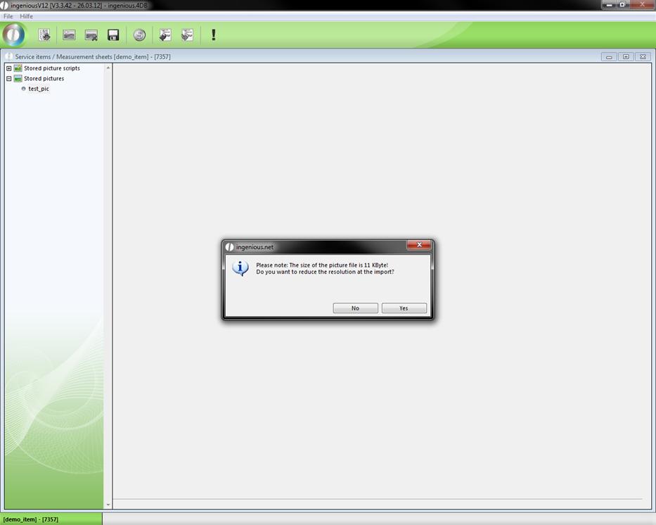
Depending on the size of the picture a dialog will be displayed where you can reduce the picture resolution.
In addition to the import you can also export picture scripts with the button ![]() .
.
The place holder {DrawPic("script name")} provides a opportunity to insert picture scripts and pictures directly into the measurement sheet, that they can be printed.